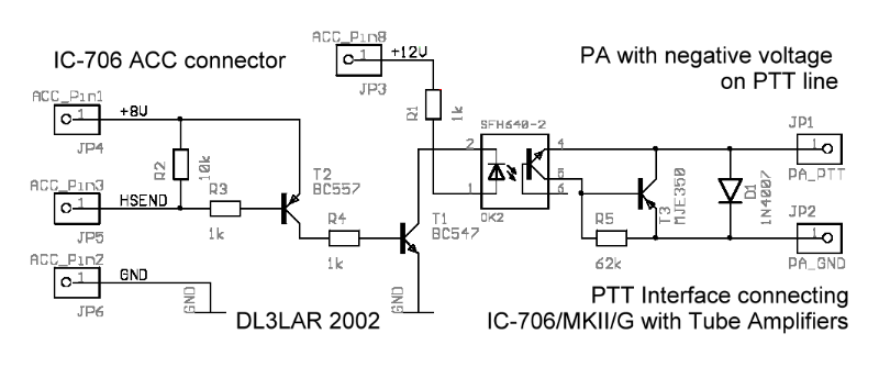
The ICOM instruction manual of the IC-706MKII [4] gives only instructions to connect a IC-4KL amplifier to the transceiver, so a solution for connecting different amplifiers has to be found. Modern solid-state linears have usally low voltage low current PTT line inputs, so a direct connection to the ACC connector of the IC-706 is possible, if the switching current is less than 20mA. Old fashion tube linear amplifiers are using the negative grid voltage for switching the PTT line instead. My goal was to develop a solid state PTT interface circuit.
First I started with taking an overview about the known information that could be claimed from the manuals. Then I completed this information by some measurements like switching times or currents.
The HSEND signal is used as bi-directional line for keying the transceiver and for switching amplifiers or antenna tuners. Its output current is limited to 200 mA and it's not designated for high negative voltages.
| signal | value |
|---|---|
| HSEND level (unkeyed) | +8 V (2k2 pull-up) |
| HSEND level (key-down) | GND (-0.5V to 0.8V) |
| HSEND input current | 20 mA |
| HSEND output current | 200 mA |
| Keydown to RF out | 10 to 12 ms |
The Collins linear [3] is using the negative grid voltage for switching the antenna relais. In the receiving state a direct connection to the transceivers HSEND line will damage the NPN transistor Q32. Even the key-down current of 60 mA is high.
| signal | value |
|---|---|
| PTT voltage (unkeyed) | -150 V |
| PTT current (key-down) | 60 mA |
| PTT relais switching time | less than 14 ms |
The idea is to use a PNP transistor which is capable to handle the required voltage and current. I choosed Motorola's MJE 350 which can be used up to 300 V and 0.5 A.
Since a common-emitter circuit needs a negative voltage for triggering I used an opto-coupler as Darlington driver. Here one have to pay attention for choosing an opto-coupler with an corresponding collector-emitter voltage [1]. Infineon's SFH640 offers 300 V [2]. An additional diode 1N4007 prevents the transistors from positive transient voltages when the relay releases.
The LED emitter of the opto-coupler should be driven with 15 mA so I decided not to use the +8V regulated output of the ACC socket because its limitation to 10 mA but the 12V output.
One additional NPN-transistor (T1) is used as LED driver to prevent both HSEND and Regulated 8V output from being damaged.

Needed parts can be directly read out from the schematic.
References:
[1] Infineon Technologies, "Driving High-Level Loads With Optocouplers - Appnote 4", 2001, www.infineon.com/opto
[2] Infineon Technologies, "SFH640 - Datasheet", 2001, www.infineon.com/opto
[3] Collins, "30L-1 Linear Amplifier instruction book", 1962, www.collinsradio.org
[4] ICOM Inc., "IC-706MKII Instruction Manual", 1997, not online available, www.icomeurope.com
Additional information on IC-706 modifications can be found at OH6KTR's pages
Icom IC-706 Resources.